
EV Charging Busbar Applications
Engineering-first custom busbars for AC and DC EV charging equipment. BusbarMFG manufactures drawing-based copper and aluminum busbars and high-current interconnects used in Level 2 AC chargers, DC fast chargers, charging cabinets, power modules, and auxiliary
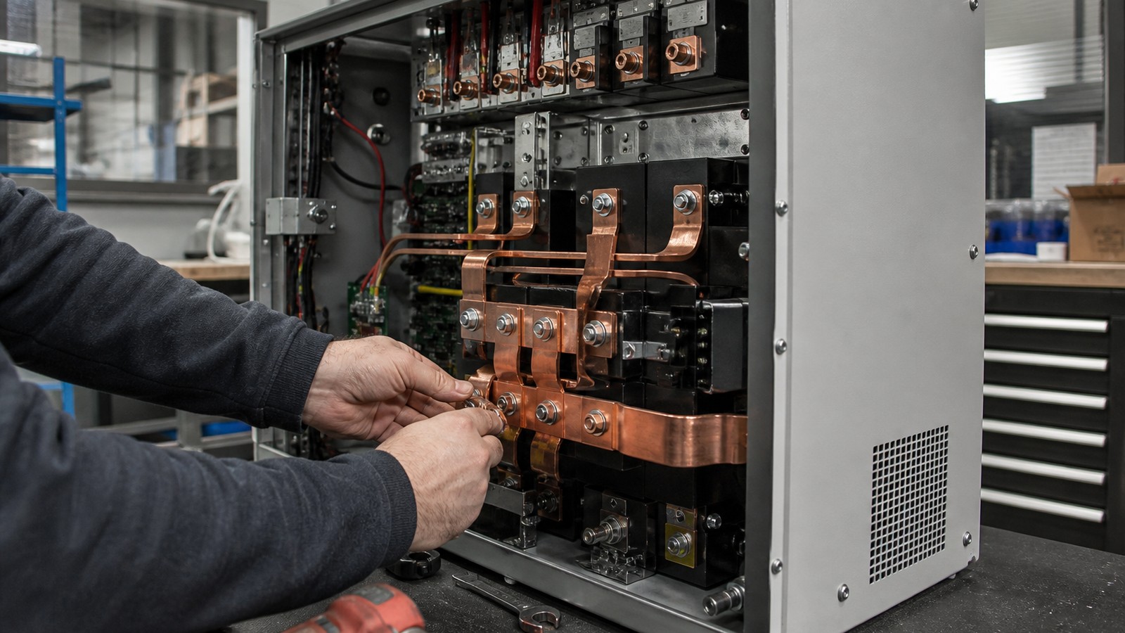
Custom busbar manufacturing
Engineering details are organized around material, tolerance, surface finish, inspection, and production readiness.
Use the inquiry module to send drawings, quantities, standards, and delivery targets for a practical manufacturing review.
Service Details
Engineering-first custom busbars for AC and DC EV charging equipment. BusbarMFG manufactures drawing-based copper and aluminum busbars and high-current interconnects used in Level 2 AC chargers, DC fast chargers, charging cabinets, power modules, and auxiliary systems.
Based in Dongguan, Guangdong, China, BusbarMFG supports engineering-led OEMs and integrators in EV charging, energy storage, and power electronics. Our workflow starts from your drawing and application requirements, moves through DFM review and prototypes, and progresses to repeat production once specifications are confirmed.
Where Busbars Are Used Inside EV Charging Systems
EV charging equipment (EVSE) contains multiple high-current paths where busbars improve thermal, electrical, and assembly performance compared to loose cables. Typical EV charging busbar applications include:
- AC input and distribution: line, neutral, and ground busbars within AC sections, switchgear, and contactor panels.
- Rectifier/PFC stage: DC busbars between rectifier or PFC modules and DC link capacitors.
- DC link and DC/DC conversion: low-inductance laminated busbars for compact, low-EMI power module connections.
- DC output to vehicle: high-current busbars connecting contactors, filters, shunts, and outlet assemblies inside DC fast charging cabinets.
- Parallel current sharing: symmetric busbar layouts to balance current across module strings or parallel rectifier bricks.
- Grounding and bonding: dedicated grounding busbars for equipment frames and cabinet sections.
- Auxiliary power and control: compact insulated busbars for low-voltage distribution inside control enclosures.
- Flexible jumpers: foil or braided flexible busbars to accommodate vibration, thermal expansion, and assembly tolerances between modules and cabinet sections.
Projects range from prototype builds for new charger platforms to supplier localization and redesign programs targeting cost, weight, packaging, or EMC improvements.
Busbar Types for EV Charging
BusbarMFG produces drawing-based parts that align with the packaging, thermal, and safety requirements of EV charging equipment:
- Copper busbars: solid flat or formed copper with optional tin, nickel, or silver plating for bolted joints and thermal environments.
- Laminated busbars: multilayer laminated structures for low-inductance power distribution between rectifier, DC/DC, and capacitor nodes.
- Insulated busbars: heat-shrink, coated, sleeved, or over-sheathed busbars for compact assemblies with defined creepage and clearance.
- Flexible busbars: stacked-foil or braided copper flexible busbars to manage movement and assembly misalignment.
- Aluminum busbars: weight- and cost-focused alternatives where aluminum is suitable for the current, thermal, and joint design.
- Custom assemblies: integrated busbars with hardware, identification, and subassembly features per drawing and BOM.
Note: CCS-integrated busbars, overmolded products, specialized welding, and other advanced processes are reviewed against the actual project and must be confirmed as available production services during technical review.
Engineering Considerations for EV Charging Busbars
EV charging applications combine high current, high voltage, and compact packaging. During DFM review, BusbarMFG evaluates:
- Current and thermal behavior: conductor cross-section, stacking, and parallel paths; temperature rise; airflow or liquid-cooled interfaces.
- Inductance and EMC: laminated busbar layer stacks and return-path alignment for low-loop inductance and reduced switching noise.
- Creepage and clearance: insulation systems and spacing strategies aligned to project voltage levels and environmental categories.
- Interfaces and connections: hole patterns, slot shapes, interface plating, torque targets, and compatibility with contactors, shunts, fuses, and modules.
- Plating and corrosion: tin for bolted joints and general environments, nickel for higher temperature, and silver where low contact resistance is prioritized.
- Insulation options: heat-shrink, powder-coated or epoxy-coated finishes, sleeves, wraps, or molded covers per drawing.
- Mechanical features: bends, offsets, formed features, stack-ups, and tolerance chains for consistent assembly.
- Copper vs. aluminum: weight and cost trade-offs, joining methods, and mixed-metal interface strategies to mitigate galvanic effects.
- Flexible sections: foil or braid jumpers to absorb cabinet tolerances, vibration, and thermal expansion without overstressing power modules or fasteners.
If your EV charging platform targets new voltage or current levels, we collaborate on prototypes and validation builds to confirm performance before committing to repeat production.
From Drawing to Production-Ready Busbars
BusbarMFG’s engineering-led workflow supports new product introduction and supplier transition programs:
1. Technical intake
- You provide drawings or 3D models, material and plating/insulation requirements, quantities, application context, and target date.
2. DFM and manufacturability review
- We review material choice, thickness, bends, holes, insulation, plating, interfaces, and connection methods. Recommendations are returned for your engineering approval.
3. Prototypes and validation
- Prototype or validation batches are produced to verify fit, form, function, and assembly repeatability.
4. Production readiness
- Once requirements are confirmed, projects move toward repeat production with agreed documentation and controls.
BusbarMFG does not publish unverified certifications, equipment lists, tolerances, lead times, production capacity, or customer claims. Project-specific requirements are confirmed during technical review.
Materials, Plating, and Insulation Options
- Materials
- Copper: common for high-current EV charging busbars.
- Aluminum: considered where mass and cost targets support aluminum with appropriate joint design.
- Plating
- Tin: widely used for bolted joints and general environments.
- Nickel: higher-temperature and wear-resistant scenarios.
- Silver: low contact resistance where specified by the design.
- Insulation
- Heat-shrink tubing and wrap systems.
- Coatings: powder coat or epoxy-based coatings per drawing requirements.
- Sleeves, tapes, and protective covers as specified.
Final plating and insulation selections are verified during engineering review with your design team.
Typical EV Charging Use Cases We Support
- Level 2 AC chargers: compact insulated busbars for AC sections, contactors, and output distribution.
- DC fast charging cabinets: high-current DC busbars, laminated DC link, output busbars to contactors and filter networks.
- Power modules: laminated busbars for rectifier/PFC and DC/DC modules with low inductance and defined creepage/clearance.
- Parallel module strings: symmetric busbars for current sharing and repeatable assembly.
- Service and maintenance designs: busbars with identification, covers, or modular subassemblies per drawing.
EV Charging Busbar DFM Checklist
To accelerate review, consider including the following in your drawing package:
- Voltage class and insulation coordination targets.
- Continuous and peak current, duty cycle, and maximum allowed temperature rise.
- Preferred material (copper or aluminum), nominal thickness, and plating.
- Insulation method and dielectric targets; creepage/clearance constraints.
- Interface details: hole sizes, slot geometry, hardware, torque requirements, and mating part numbers.
- Mechanical constraints: bend radii, offsets, cabinet clearances, and integration with contactors, shunts, fuses, and capacitors.
- Prototype versus production intent, quantities, and target timeline.
Who We Serve
BusbarMFG focuses on engineering-led OEMs and integrators:
- EVSE manufacturers, DC fast charger builders, and charging cabinet integrators.
- Battery module and pack companies integrating onboard or depot charging.
- Inverter/PCS/UPS and power electronics OEMs with shared busbar requirements.
- Switchgear and industrial power manufacturers managing high-current distribution in compact spaces.
Ideal programs include new platforms, redesigns, localization, supplier replacement, cable-to-busbar conversions, copper-to-aluminum evaluations, and low-inductance power module connections.
Request Pricing for EV Charging Busbar Applications
Share drawings, material grade, tolerance, surface finish, quantity, and delivery schedule. BusbarMFG will review the requirement and respond with the next step.
Engineering RFQ
Upload Your Drawing
Share drawings or models, material, plating or insulation requirements, quantity, application, and target date. We will review the technical requirements before confirming manufacturing options.
Email: info@busbarmfg.com
Address: Huali Industrial Park, Xianghe Road, Dalang Town, Dongguan City, Guangdong Province, China