
Busbar Insulation and Overmolding
Engineering-first insulation and overmolding solutions for copper and aluminum busbars and battery interconnects in EV, ESS, power electronics, charging equipment, switchgear, and industrial power applications.
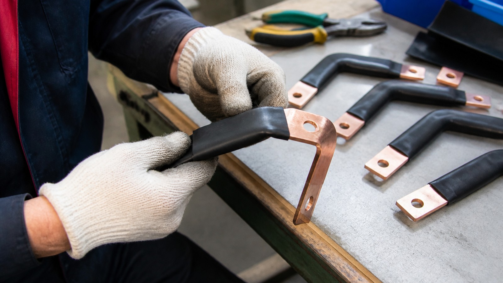
Custom busbar manufacturing
Engineering details are organized around material, tolerance, surface finish, inspection, and production readiness.
Use the inquiry module to send drawings, quantities, standards, and delivery targets for a practical manufacturing review.
Service Details
Engineering-first insulation and overmolding solutions for copper and aluminum busbars and battery interconnects in EV, ESS, power electronics, charging equipment, switchgear, and industrial power applications.
Overview
BusbarMFG manufactures drawing-based insulated and overmolded busbars to help engineering-led OEMs route high current safely in compact assemblies. Our team reviews each project’s electrical, thermal, mechanical, and assembly requirements to define suitable materials, insulation thicknesses, interfaces, and manufacturing processes. Projects typically begin with prototypes or validation builds and progress to repeat production as specifications are confirmed.
All insulation and overmolding projects are confirmed against the actual application during technical review.
Insulation Options
Insulated busbars protect against accidental contact, improve creepage and clearance, control arc risk, and simplify assembly. Depending on your drawing and application, reviewed options may include:
- Heat-shrink insulation
- Polyolefin or specialty heat-shrink applied to straight or formed busbars
- Selectable wall thicknesses, colors (including EV orange), and temperature ratings
- Sleeved and wrapped insulation
- PET and fabric sleeves, fiberglass silicone sleeves, or tape-wrap constructions
- Useful for flexible busbars and assemblies requiring vibration accommodation
- Coated busbars
- Dip, spray, or powder-coated finishes (e.g., epoxy-based systems) for uniform coverage
- Masked regions for terminations, fasteners, welds, or test points
- Laminated busbars
- Multilayer copper or aluminum conductors separated by dielectrics
- Common industry dielectrics include PET, polyimide films, and epoxy-glass systems
- Targets low inductance and compact packaging in inverters, PCS, UPS, and power modules
Material choices, thicknesses, and process controls are defined during engineering review to meet creepage/clearance, dielectric withstand, temperature rise, and integration requirements.
Overmolding for Busbars
Overmolding adds a molded polymer layer or structure around the busbar to create integrated insulation, mechanical features, and assembly guides. Typical objectives include:
- High-voltage touch-safe covers with defined creepage/clearance
- Integrated strain relief, keying, and alignment features
- Ribs, windows, and bosses for fasteners, studs, and sensors
- Color coding (e.g., HV orange) for service identification
Project-dependent polymer selections may include engineering thermoplastics (e.g., PA, PBT, PPS, LCP) or elastomeric materials (e.g., TPU/TPE), reviewed against thermal environment, dielectric needs, flame rating targets, and chemical exposure.
Note: Overmolded products are evaluated case-by-case and confirmed during technical review to validate feasibility, tooling approach, and production method.
Applications
- EV battery modules and packs: high-current interconnects with HV insulation, compact routing, and weld/bolt interfaces
- Energy storage systems (ESS): laminated busbars and insulated copper/aluminum links for PCS and battery cabinets
- Power electronics (inverters, UPS, rectifiers): low-inductance laminated busbars, molded covers, and masked terminals
- Charging and power distribution equipment: touch-safe insulated busbars and assemblies for limited-space panels
- Switchgear and industrial power: coated or sleeved busbars with stable thermal and mechanical performance
Engineering Considerations and DFM Guidance
To accelerate review and deliver manufacturable drawings, consider:
- Creepage and clearance
- Define target creepage and clearance distances per system voltage and standards
- Indicate required test methods (e.g., dielectric withstand / hipot) and acceptance criteria
- Insulation thickness and coverage
- Specify insulated zones vs. masked contact areas (lugs, weld tabs, press-fit regions)
- Identify edge conditions (break edges, chamfers, radii) to avoid cutting or thinning insulation
- Material compatibility
- State base material (copper, aluminum), plating (tin, nickel, silver), and process order
- Confirm chemical exposure, temperature range, and flame rating objectives
- Mechanical features
- Overmolded ribs, alignment keys, windows, and fastener bosses as defined in CAD
- Allow for tolerance stack-up across busbar, insulation, and molded features
- Thermal and electrical performance
- Provide current profile, allowable temperature rise, and duty cycle
- Note inductance targets for laminated busbars where switching performance matters
- Assembly and test
- Define assembly sequence, tooling clearance, service access, and test points
- Outline inspection (visual coverage, adhesion), electrical test (hipot, continuity), and packaging needs
All tolerances, materials, and process controls are confirmed for the specific project during technical review.
Typical Insulation and Overmolding Interfaces
- Masked pads for bolted joints and welded tabs
- Windows for sensors, studs, or busbar measurement points
- Integrated barriers, standoffs, and cable guides
- HV orange and other color requirements for service identification
- Labeling, part marks, and orientation features aligned to assembly
Project Workflow
- Drawing-based review
- Provide 2D/3D models, material and plating details, insulation and overmolding requirements, quantities, application notes, and timeline
- Engineering quotation
- BusbarMFG assesses manufacturability and proposes an engineering quotation aligned to the project phase (prototype, validation, repeat production)
- Prototypes and validation
- Iterative builds to confirm material, coverage, creepage/clearance, assembly fit, and test performance
- Repeat production
- Transition to consistent production once specifications and quality criteria are confirmed
BusbarMFG does not publish unverified certifications, equipment lists, tolerances, lead times, production capacity, or customer claims. Project-specific requirements are confirmed during technical review.
RFQ Checklist
To enable an efficient review for Busbar Insulation and Overmolding:
- CAD data
- 2D drawings and/or 3D models with dimensions and GD&T for busbar and any molded features
- Electrical requirements
- System voltage, creepage/clearance targets, dielectric test requirements, color coding (e.g., HV orange)
- Materials and finishes
- Base metal (copper/aluminum), thickness, plating (tin, nickel, silver), insulation type(s), overmold polymer preferences
- Mechanical and assembly
- Hole sizes, bends, interfaces, studs, weld tabs, masked regions, assembly sequence
- Environment and compliance
- Temperature range, vibration, chemical exposure, flame rating objectives, relevant standards
- Program details
- Quantity (prototype/validation/production), target dates, decision-maker contact, and application context
Request Pricing for Busbar Insulation and Overmolding
Share drawings, material grade, tolerance, surface finish, quantity, and delivery schedule. BusbarMFG will review the requirement and respond with the next step.
Engineering RFQ
Upload Your Drawing
Share drawings or models, material, plating or insulation requirements, quantity, application, and target date. We will review the technical requirements before confirming manufacturing options.
Email: info@busbarmfg.com
Address: Huali Industrial Park, Xianghe Road, Dalang Town, Dongguan City, Guangdong Province, China