
CCS Integrated Busbar
Engineering-first, drawing-based busbar manufacturing for CCS charging inlets and DC fast-charging assemblies. BusbarMFG supports engineering-led OEMs developing EV chargers, on-vehicle CCS inlet modules, battery packs, and power electronics where compact, low
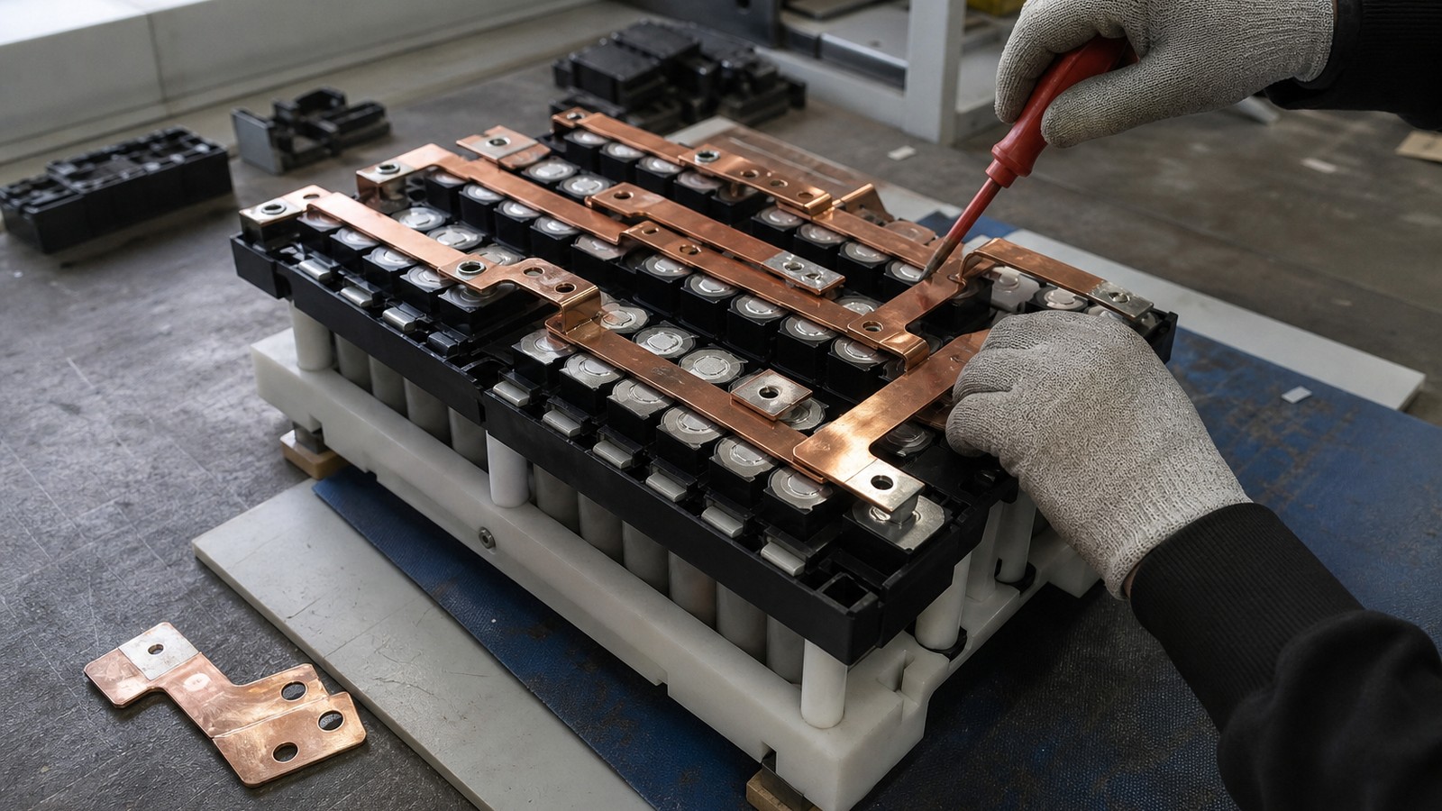
Custom busbar manufacturing
Engineering details are organized around material, tolerance, surface finish, inspection, and production readiness.
Use the inquiry module to send drawings, quantities, standards, and delivery targets for a practical manufacturing review.
Service Details
Engineering-first, drawing-based busbar manufacturing for CCS charging inlets and DC fast-charging assemblies. BusbarMFG supports engineering-led OEMs developing EV chargers, on-vehicle CCS inlet modules, battery packs, and power electronics where compact, low-inductance, and thermally stable high-current paths are required.
BusbarMFG manufactures custom copper and aluminum busbars and related interconnects from your drawings and application requirements. CCS integrated busbars and other specialized or overmolded configurations are reviewed against the actual project and confirmed on a case-by-case basis before they are represented as available production services.
What Is a CCS Integrated Busbar?
A CCS integrated busbar is a high-current conductor designed to fit inside or adjacent to CCS charging interfaces (Combo 1/Combo 2) on the vehicle or charging equipment side. It typically routes DC power between:
- The CCS inlet DC pins and contactors/fuses/DC link inside a vehicle or battery module enclosure.
- The DC rectification stage and the CCS output interface inside DC fast chargers (HPC, depot, and public charging cabinets).
These busbars are engineered to:
- Carry high continuous and peak currents within defined temperature rise limits.
- Meet creepage and clearance targets for the application’s voltage class.
- Achieve compact packaging with low inductance to reduce switching and EMI effects in power electronics.
- Provide reliable mechanical interfaces to connectors, studs, contactors, and power modules.
Typical Configurations We Review
All configurations are project-reviewed and drawing-based. Representative options include:
- Solid copper busbars: flat or formed profiles with tin, nickel, or silver plating per spec.
- Insulated busbars: heat-shrink, coating, or sleeving to achieve clearances and improve assembly safety.
- Laminated busbars: multilayer, low-inductance structures for compact power distribution.
- Flexible links: copper foil or braid elements to accommodate vibration and assembly tolerance stack-ups.
- Integration features: alignment holes, locator tabs, isolation barriers, and carrier-ready profiles.
- Overmold-ready or carrier-mounted busbars: require feasibility review and confirmation.
Note: Welding, overmolding, certain stamping/forming methods, and other specialized processes must be reviewed against the project and confirmed capability before being offered as production services.
Materials and Surface Finishes
- Materials: High-conductivity copper or aluminum, selected based on current density, thermal rise, mass targets, and cost tradeoffs.
- Plating: Tin, nickel, or silver per drawing to balance conductivity, corrosion resistance, mating wear, and contact resistance.
- Insulation: Heat-shrink, powder coating, sleeves, or selective insulation to meet creepage, clearance, and assembly requirements.
Final materials, finishes, and insulation systems are confirmed during technical review.
Design Considerations for CCS Integrated Busbars
- Current and thermal performance
- Continuous and peak current, duty cycle, ambient and enclosure conditions, airflow or cooling strategy, target temperature rise.
- Voltage class and spacing
- Creepage and clearance targets, insulation thickness, partial discharge considerations, and dielectric test requirements.
- Inductance and EMC
- Conductor geometry, parallel path balance, return paths, and laminated structures for low loop inductance.
- Mechanical interfaces
- CCS inlet DC pin interfaces, contactors, fuse/pyro-fuse, studs, threaded inserts, torque specs, and assembly sequence.
- Plating and corrosion environment
- Selection for contact resistance, durability, and environmental exposure.
- Manufacturing and inspection
- Bend radii, formed features, slotting, press-fit or staked interfaces, and inspection points defined on the drawing.
Applications We Support
- EV charging equipment
- DC fast chargers (HPC), depot and fleet chargers, charging cabinets, and power conversion systems.
- Vehicle-side CCS inlet integration
- Busbars between CCS inlet DC pins and high-voltage junction boxes, contactors, and DC link capacitors.
- Energy storage and power electronics
- High-current DC paths in PCS, UPS, and inverter systems where CCS-connected infrastructure is part of the application ecosystem.
From Drawing to Production-Ready Busbars
- Engineering review
- We assess manufacturability, materials, plating, insulation, bends, holes, interfaces, and connection methods against your application.
- Prototypes and validation
- Projects typically begin with prototypes or validation batches for fit, function, and customer testing.
- Repeat production
- After requirements are confirmed, we support controlled ramp to repeat production, maintaining drawing fidelity and change control.
BusbarMFG does not publish unverified certifications, equipment lists, tolerances, lead times, production capacity, or customer claims. Project-specific requirements are confirmed during technical review.
What to Include in a CCS Busbar RFQ
Providing complete technical data enables faster and more accurate engineering feedback:
- Drawings or 3D models with revision and BOM references.
- Electrical requirements
- Continuous/peak current, duty cycle, allowable temperature rise, voltage class, dielectric or hipot requirements.
- Mechanical and assembly details
- Interfaces to CCS inlet pins, contactors, studs, fasteners; torque specs; mounting scheme; assembly sequence notes.
- Insulation and spacing
- Creepage/clearance targets, insulation type and thickness, color or marking needs, masking or selective insulation.
- Materials and finishing
- Copper/aluminum, plating (tin/nickel/silver), surface treatment, corrosion environment.
- Dimensional constraints
- Envelope limits, bend radii, tolerances, critical-to-quality features, datum scheme.
- Validation and quality notes
- Prototype test plan references (e.g., fit check, torque validation, electrical tests), sampling expectations, documentation needs.
- Quantity and timeline
- Prototype and pilot quantities, estimated annual usage, target dates.
Why Engineering-Led OEMs Choose BusbarMFG
- Drawing-based manufacturing across copper and aluminum busbars, insulated/laminated structures, and flexible links.
- Practical DFM feedback aligned to EV charging, ESS, and power electronics constraints.
- Prototype-to-production support with transparent technical communication and drawing confidentiality.
- Focus on dimensional consistency, plating and insulation quality, and assembly readiness for repeat builds.
Request Pricing for CCS Integrated Busbar
Share drawings, material grade, tolerance, surface finish, quantity, and delivery schedule. BusbarMFG will review the requirement and respond with the next step.
Engineering RFQ
Upload Your Drawing
Share drawings or models, material, plating or insulation requirements, quantity, application, and target date. We will review the technical requirements before confirming manufacturing options.
Email: info@busbarmfg.com
Address: Huali Industrial Park, Xianghe Road, Dalang Town, Dongguan City, Guangdong Province, China