
Busbar Case Studies
The examples below are hypothetical engineering scenarios, not customer case studies and not claims about completed BusbarMFG projects. They illustrate the questions that commonly need to be resolved before a custom busbar can be quoted and manufactured.
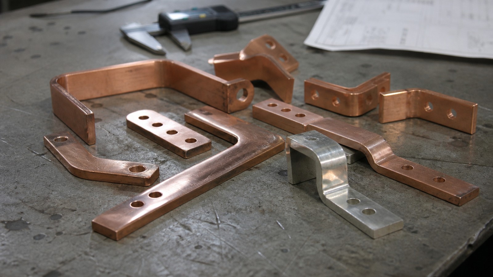
Custom busbar manufacturing
Engineering details are organized around material, tolerance, surface finish, inspection, and production readiness.
Use the inquiry module to send drawings, quantities, standards, and delivery targets for a practical manufacturing review.
Service Details
The examples below are hypothetical engineering scenarios, not customer case studies and not claims about completed BusbarMFG projects. They illustrate the questions that commonly need to be resolved before a custom busbar can be quoted and manufactured.
BusbarMFG does not publish unverified customer names, project results, certifications, equipment, tolerances, lead times, or production capacity. Actual feasibility and capability are confirmed from the customer drawing and application requirements.
Scenario 1: EV Battery Module Interconnect
An EV battery interconnect may need compact routing, controlled creepage and clearance, repeatable terminal alignment, and stable bolted or welded interfaces.
Important RFQ inputs include:
- Electrical current and temperature-rise targets
- Material and thickness
- Hole, bend, and terminal datums
- Plating or surface-treatment requirements
- Insulation coverage and cutback map
- Joint method, hardware stack, and torque or weld requirements
- Validation and reporting requirements
The engineering review should determine which requirements can be manufactured and inspected for the specific design.
Scenario 2: ESS or Inverter Laminated Busbar
A laminated busbar may be considered when packaging density and loop inductance are important. The RFQ should define the conductor stack, dielectric system, interfaces, creepage and clearance, and electrical validation method.
Questions to resolve include layer registration, pad and hole geometry, insulation edges, mounting clearances, thermal conditions, and the method used to verify electrical performance. Lamination and testing capabilities must be confirmed for the actual project.
Scenario 3: Copper-to-Aluminum Evaluation
Changing from copper to aluminum can affect cross-section, temperature rise, stiffness, oxidation, joint design, plating, and galvanic compatibility. It should not be treated as a direct material substitution.
The RFQ should include current, duty cycle, allowable temperature rise, envelope limits, joint stack, environmental conditions, surface treatment, and validation criteria. Final material selection remains the customer's engineering decision after project-specific review and testing.
Scenario 4: Cable-to-Busbar Redesign
A formed busbar can provide defined routing and fixed interfaces, but it also transfers tolerance and movement into the assembly. A redesign review should consider bend geometry, mounting points, assembly sequence, service access, vibration, thermal expansion, and error-proofing features.
Provide the existing cable route, mating components, enclosure constraints, current profile, and installation process so manufacturability can be assessed.
Scenario 5: Flexible Busbar for Movement or Tolerance Stack-Up
Flexible foil or braided structures may be evaluated where movement, vibration, or assembly variation must be accommodated. The required electrical path, terminal design, flex zone, insulation, movement envelope, and life-cycle validation should be defined.
Foil count, braid construction, joining process, and test method are project-specific. Availability and validation scope are confirmed during technical review.
Scenario 6: Insulated Busbar in Compact Switchgear
Compact routing can make creepage, clearance, edge protection, cutbacks, and assembly sequencing critical. The drawing should clearly distinguish conductive contact zones from insulated zones and define the insulation system and any dielectric test.
Share voltage, pollution/environment assumptions, spacing requirements, mating hardware, and applicable standards. BusbarMFG can then review the drawing and confirm what can be quoted.
Scenario 7: Charging or Industrial Power Distribution
High-current distribution designs often depend on conductor cross-section, mounting span, joint area, enclosure airflow, surface treatment, and accessible assembly. The RFQ should define current profile, temperature-rise criteria, mounting, contact interfaces, allowable envelope, and required verification.
No performance outcome should be assumed until the design has been analyzed and validated under the customer's defined conditions.
A Practical Drawing-to-Quotation Workflow
1. Submit the current drawing or model and project requirements.
2. Identify material, finish, insulation, interfaces, and critical dimensions.
3. Define electrical, thermal, mechanical, and documentation requirements.
4. Review manufacturability and clarify specialized operations.
5. Confirm feasibility, inspection scope, quotation, and schedule.
6. If ordered, use prototypes or validation units for the customer's qualification process before repeat production.
CCS integrated busbars, overmolding, welding, stamping, forming, lamination, and other specialized operations are evaluated case by case and are not represented as available until confirmed.
Request Pricing for Busbar Case Studies
Share drawings, material grade, tolerance, surface finish, quantity, and delivery schedule. BusbarMFG will review the requirement and respond with the next step.
Engineering RFQ
Upload Your Drawing
Share drawings or models, material, plating or insulation requirements, quantity, application, and target date. We will review the technical requirements before confirming manufacturing options.
Email: info@busbarmfg.com
Address: Huali Industrial Park, Xianghe Road, Dalang Town, Dongguan City, Guangdong Province, China