
Busbar Current Calculator
A busbar current calculation is an early sizing exercise, not a final production approval. Current capacity depends on conductor material, cross section, ambient temperature, enclosure, airflow, duty cycle, surface condition, joints, insulation, spacing, and t
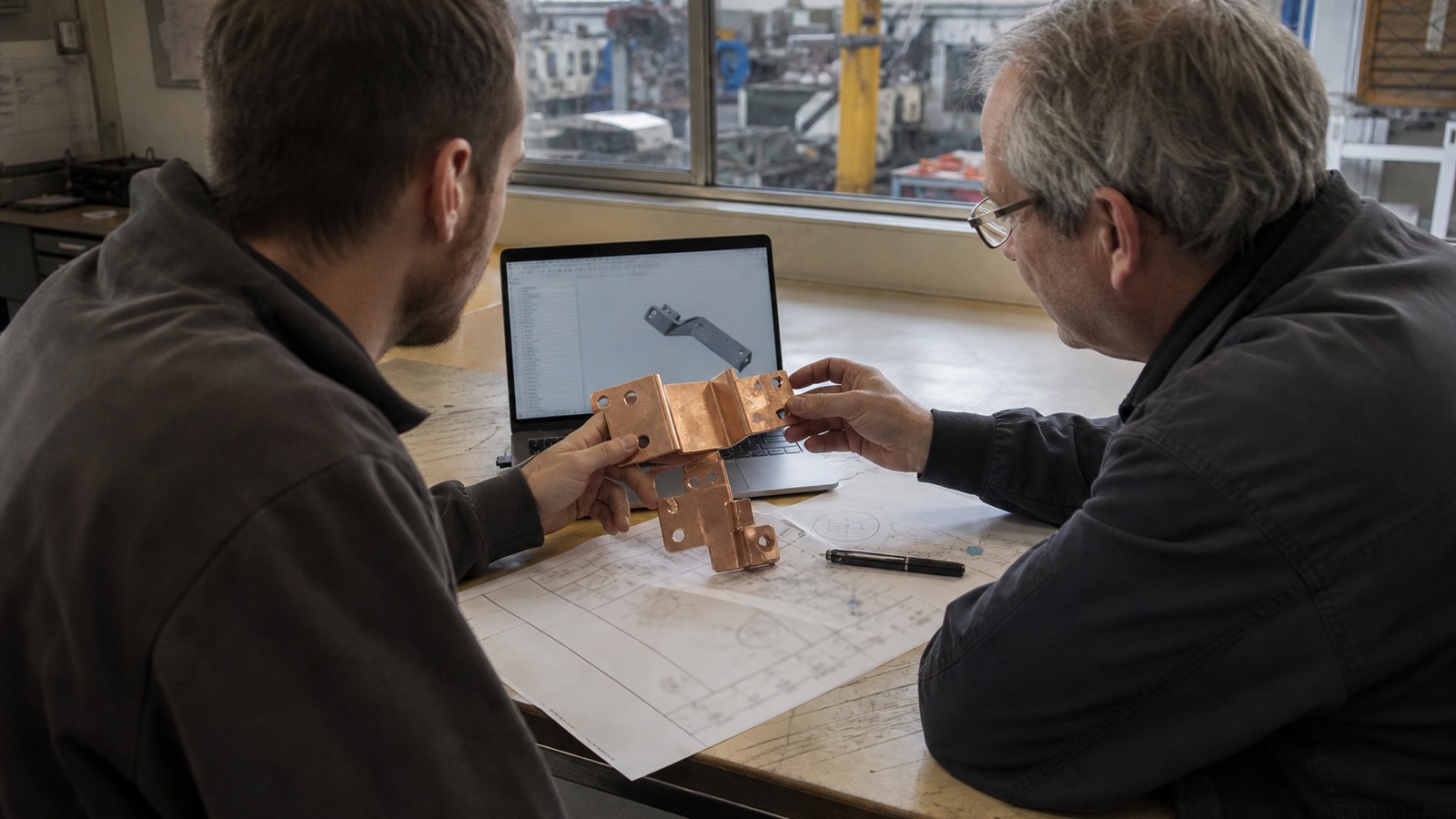
Custom busbar manufacturing
Engineering details are organized around material, tolerance, surface finish, inspection, and production readiness.
Use the inquiry module to send drawings, quantities, standards, and delivery targets for a practical manufacturing review.
Service Details
A busbar current calculation is an early sizing exercise, not a final production approval. Current capacity depends on conductor material, cross section, ambient temperature, enclosure, airflow, duty cycle, surface condition, joints, insulation, spacing, and the permitted temperature rise. BusbarMFG uses the customer's electrical and mechanical requirements as the starting point for an engineering review.
Screening Formula
For an initial cross-section estimate:
Required conductor area = Design current / Selected current-density assumption
The result is an initial area in square millimetres when current is entered in amperes and the current-density assumption is entered in amperes per square millimetre. The assumption must come from the applicable design method, standard, validated reference design, or project-specific thermal study. This page does not prescribe a universal current-density value.
For a rectangular bar:
Cross-sectional area = Width × Thickness
Possible width and thickness combinations must then be checked against packaging, bending, hole and slot geometry, edge distances, creepage and clearance, joint design, insulation, forming, and assembly constraints.
Inputs to Prepare
- Continuous current and short-duration peak current
- Duty cycle and peak duration
- Copper or aluminum material specification
- Maximum ambient temperature
- Allowable conductor and joint temperature rise
- Natural convection, forced airflow, liquid cooling, or enclosed operation
- Available width, thickness, and routing envelope
- Number, location, and geometry of joints
- Plating, insulation, coating, or overmolding requirements
- Installation orientation and spacing to nearby conductors
- Applicable product, safety, and customer standards
Why One Number Is Not Enough
Two busbars with the same cross-sectional area can operate differently. A wide, thin bar has a different exposed surface area and current distribution from a narrow, thick bar. Enclosures restrict heat rejection. Closely spaced phases interact thermally. Bends, holes, joints, and contact interfaces create local conditions that a simple area calculation does not capture.
Use the screening result to compare feasible geometries, then validate the selected design with the project-specific electrical, thermal, mechanical, and compliance requirements.
Copper and Aluminum Review
Copper and aluminum should not be treated as interchangeable by area alone. Material selection affects conductivity, density, thermal behaviour, joint design, surface preparation, plating compatibility, galvanic considerations, mechanical strength, and packaging. When weight, cost, or space drives a material comparison, review the complete connection system rather than only the conductor body.
Joint and Interface Checks
The conductor body may not be the limiting part of a busbar assembly. Review:
- Contact surface condition and plating specification
- Fastener and washer arrangement
- Hole and slot tolerances from the drawing
- Contact pressure and assembly method
- Dissimilar-material interfaces
- Expected vibration and thermal cycling
- Inspection and validation requirements
Project-specific joint resistance and temperature-rise acceptance criteria must be defined and verified by the responsible engineering team.
Engineering Review Workflow
1. Define the electrical load case, environment, and applicable standards.
2. Calculate an initial conductor area using an approved project assumption.
3. Select practical width and thickness combinations.
4. Add bends, holes, joints, insulation zones, and assembly interfaces.
5. Review manufacturability against the drawing.
6. Validate electrical, thermal, mechanical, and compliance performance.
7. Release the design only after project-specific evidence is accepted.
Important Limitation
This worksheet is educational and supports early RFQ preparation. It is not a certified calculator, does not establish a guaranteed ampacity, and does not replace engineering analysis, simulation, testing, applicable standards, or approval by the responsible designer.
Request a Drawing Review
To prepare a practical manufacturing review, provide the drawing or model, current and duty-cycle requirements, material, available envelope, joint details, insulation or plating requirements, applicable standards, quantity, and project phase. BusbarMFG will review the supplied requirements before confirming manufacturing options.
Request Pricing for Busbar Current Calculator
Share drawings, material grade, tolerance, surface finish, quantity, and delivery schedule. BusbarMFG will review the requirement and respond with the next step.
Engineering RFQ
Upload Your Drawing
Share drawings or models, material, plating or insulation requirements, quantity, application, and target date. We will review the technical requirements before confirming manufacturing options.
Email: info@busbarmfg.com
Address: Huali Industrial Park, Xianghe Road, Dalang Town, Dongguan City, Guangdong Province, China