
Busbar Design Guide
An engineering-first guide to specifying and sourcing custom copper and aluminum busbars for EV battery systems, energy storage, power electronics, charging equipment, switchgear, and industrial power distribution.
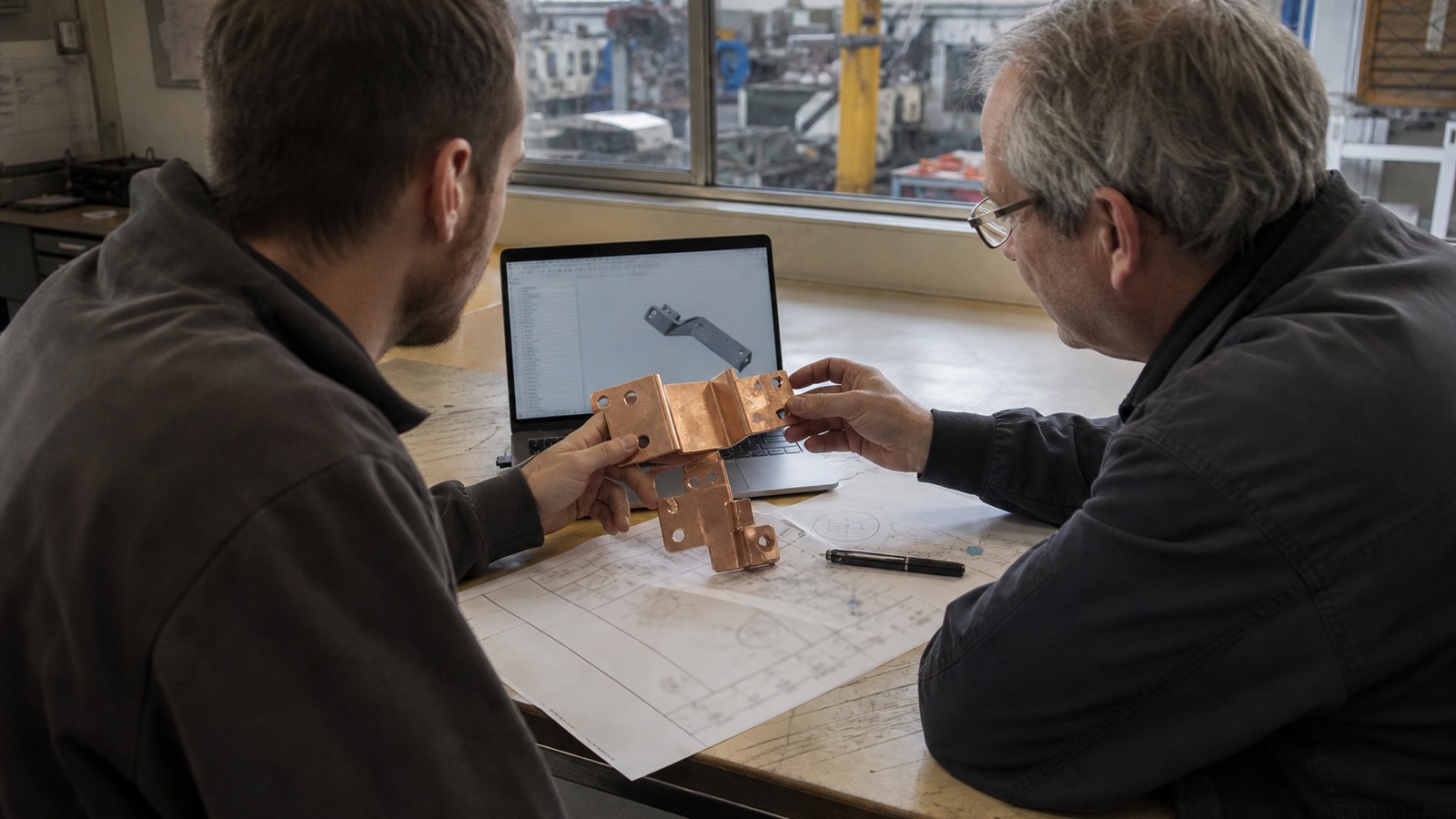
Custom busbar manufacturing
Engineering details are organized around material, tolerance, surface finish, inspection, and production readiness.
Use the inquiry module to send drawings, quantities, standards, and delivery targets for a practical manufacturing review.
Service Details
An engineering-first guide to specifying and sourcing custom copper and aluminum busbars for EV battery systems, energy storage, power electronics, charging equipment, switchgear, and industrial power distribution.
BusbarMFG is a drawing-based manufacturer in Dongguan, Guangdong, China. We turn your prints and requirements into production-ready copper and aluminum busbars, flexible links, insulated and laminated structures, and battery interconnect components. This Busbar Design Guide helps engineering-led buyers move efficiently from concept to prototypes and repeat production.
Who This Busbar Design Guide Is For
- Electrical, mechanical, battery pack, and power electronics engineers
- R&D, NPI, sourcing, and commodity managers
- EV, ESS, inverter/PCS/UPS, charger, switchgear, and industrial power OEMs
- Teams launching new platforms, redesigning for cost/weight, or replacing suppliers
From Drawing to Production-Ready Busbars
Our process begins with your drawing or model and application requirements. We provide an engineering review focused on manufacturability and application fit:
- Materials and thickness
- Plating and insulation
- Bends, holes, slots, and edge conditions
- Interfaces: fasteners, terminals, lugs, welds
- Assembly method and production risks
Programs often start with prototypes or validation lots and progress to repeat production once requirements are confirmed.
Product Scope Reference
- Copper busbars: solid, flat, or formed; bare or tin/nickel/silver plated
- Flexible busbars: foil stacks, braided shunts, and insulated flexible links
- Insulated busbars: heat-shrink, coated, sleeved, or over-sheathed assemblies
- Laminated busbars: multilayer, low-inductance power distribution structures
- Battery busbars: cell/module/pack interconnects for EV and ESS
- Aluminum busbars: weight- and cost-optimized conductors
- Custom busbar assemblies: drawing-based high-current interconnect components
Note: CCS integrated busbars, overmolded products, welding, stamping, forming, and other specialized processes are reviewed against actual project requirements and confirmed before they are represented as available production services.
Core Decisions in Busbar Design
Use this Busbar Design Guide as a checklist during concept and drawing work. Project-specific values are confirmed in our technical review.
- Current and thermal performance
- Define continuous and peak current, duty cycle, ambient range, allowable temperature rise, and cooling environment.
- Estimate I²R losses, consider parallel paths, and plan for hot spots near joints and bends.
- Validate with prototyping and temperature mapping under worst-case conditions.
- Conductor material: copper vs. aluminum
- Copper: high conductivity, compact cross-sections, established plating systems for bolted interfaces.
- Aluminum: lighter and cost-effective at larger cross-sections; consider joint design, corrosion mitigation, and plating or interface hardware suitable for Al.
- For mixed-metal systems, specify appropriate joining methods and protection against galvanic corrosion.
- Thickness and cross-section
- Size cross-section to meet current density and temperature rise targets while maintaining mechanical stiffness.
- For long parts or vibration environments, evaluate deflection and add features (ribs, bends, or supports) as needed.
- Plating and surface finish
- Tin: common for bolted connections, good cost/performance, suitable for Cu and select Al solutions via proper underlayers.
- Nickel: higher hardness and corrosion resistance; often used as an underlayer or for high-temperature environments.
- Silver: excellent conductivity and contact performance; consider cost and tarnish behavior.
- Define plated regions, thickness range, and mask lines on the drawing; call out base material condition (e.g., oxygen-free, ETP, temper).
- Insulation and electrical spacing
- Options: heat-shrink, dip or spray coatings, sleeves, laminated films, or molded covers.
- Define dielectric strength, thickness target, operating temperature class, and color/marking.
- Maintain creepage and clearance appropriate to system working voltage and pollution degree; specify measurement method and reference surfaces.
- Geometry: bends, holes, slots, and edges
- Choose bend radii and angles compatible with the chosen material and thickness.
- Position holes and slots to support load paths and minimize stress concentrations.
- Deburr, chamfer, and radius edges to protect insulation and hands during assembly.
- Interfaces and joints
- Bolted joints: define hole pattern, fastener class, washer scheme, torque, and required contact area/plating.
- Welded joints (e.g., ultrasonic, projection, resistance), rivets, or busbar-to-cable transitions: specify process intent and access constraints.
- For Cu–Al transitions, consider bimetallic elements, solid-state welds, or mechanically reinforced interfaces designed for corrosion control.
- Low-inductance and laminated busbars
- Reduce loop area by layering positive and negative conductors with consistent overlap.
- Use dielectric films with defined thickness and thermal properties.
- Plan via transitions and tab locations to minimize parasitic inductance and uneven current sharing.
- Flexibility and vibration
- Use foil stacks or braided flexible links where thermal expansion, tolerance stack-ups, or vibration demand compliance.
- Define required stroke, stiffness targets, and cycle life expectations.
DFM Rules of Thumb (Confirm During Technical Review)
These early-stage guidelines support modeling and preliminary drawings. Actual manufacturability and tolerances are confirmed after reviewing your design and application.
- Bend radius: start with inside radius on the order of the material thickness or larger to reduce work hardening and springback.
- Hole size: avoid hole diameters smaller than material thickness without process justification; keep holes larger when threads or hardened fasteners are used.
- Edge distances: target hole-to-edge spacing around one to two material thicknesses or greater to maintain strength and plating quality.
- Slot width: keep slot widths comfortably above the punch width needed for your thickness; avoid very long, narrow slots without reliefs.
- Feature spacing: maintain adequate web widths between holes, slots, and bends to control distortion.
- Flatness and twist: add ribs or intermediate bends to stiffen large, thin parts; specify functional flatness only where it matters.
- Plating masks: provide clear mask lines or keep-out zones to avoid unwanted plating in insulated or weld regions.
- Insulation: allow extra clearance at sharp corners and near fasteners; specify abrasion resistance where tools contact insulation.
Battery Busbar Considerations
- Cell connection strategy: studs/bolts, welds (laser, ultrasonic), or press-fit hardware; define access and serviceability.
- Voltage and spacing: set creepage/clearance and insulation class for pack working voltage and environment.
- Sensing and auxiliary features: integrate voltage taps, fusing, shunt elements, or NTCs with defined attachment points and insulation breaks.
- Pack assembly: design for tolerance stack-ups across modules; use flexible links where frames and trays shift during thermal cycling.
- Corrosion and contamination: specify surface protection and sealing for coolant exposure, condensation, or salt spray environments.
Drawing and Documentation Checklist
Include these items to accelerate review and quotation:
- 2D drawing (PDF) and 3D model (STEP/Parasolid)
- Material spec and temper; copper grade or aluminum alloy
- Thickness, finished dimensions, and any critical GD&T
- Plating type, thickness, and masked regions
- Insulation type, thickness target, color, and coverage map
- Bend angles, radii, and formed state dimensions
- Hole/slot sizes, tolerances, and positional datums
- Interface details: fasteners, torque, washers, lugs, weld symbols, or bimetal elements
- Electrical requirements: current profile, allowable temperature rise, voltage class
- Environment: operating temperature, vibration, ingress, corrosion expectations
- Quantity by phase: prototypes, validation, and anticipated repeat orders
- Packaging, labeling, and ESD or cleanliness requirements
- Required tests or validations at supplier vs. at your site
If you need a neutral drawing template for busbars, ask us and we will provide one.
Prototype-to-Production Path
- Feasibility and DFM review
- Prototype fabrication to validate fit, function, and thermal performance
- Iteration on plating/insulation and interfaces based on test results
- Validation lots with agreed inspection and documentation
- Ramp to repeat production once requirements are stable
Request Pricing for Busbar Design Guide
Share drawings, material grade, tolerance, surface finish, quantity, and delivery schedule. BusbarMFG will review the requirement and respond with the next step.
Engineering RFQ
Upload Your Drawing
Share drawings or models, material, plating or insulation requirements, quantity, application, and target date. We will review the technical requirements before confirming manufacturing options.
Email: info@busbarmfg.com
Address: Huali Industrial Park, Xianghe Road, Dalang Town, Dongguan City, Guangdong Province, China