
Busbar Insulation Guide
Engineering-first guidance for specifying insulated copper and aluminum busbars used in EV battery systems, energy storage, power electronics, charging equipment, switchgear, and industrial power distribution.
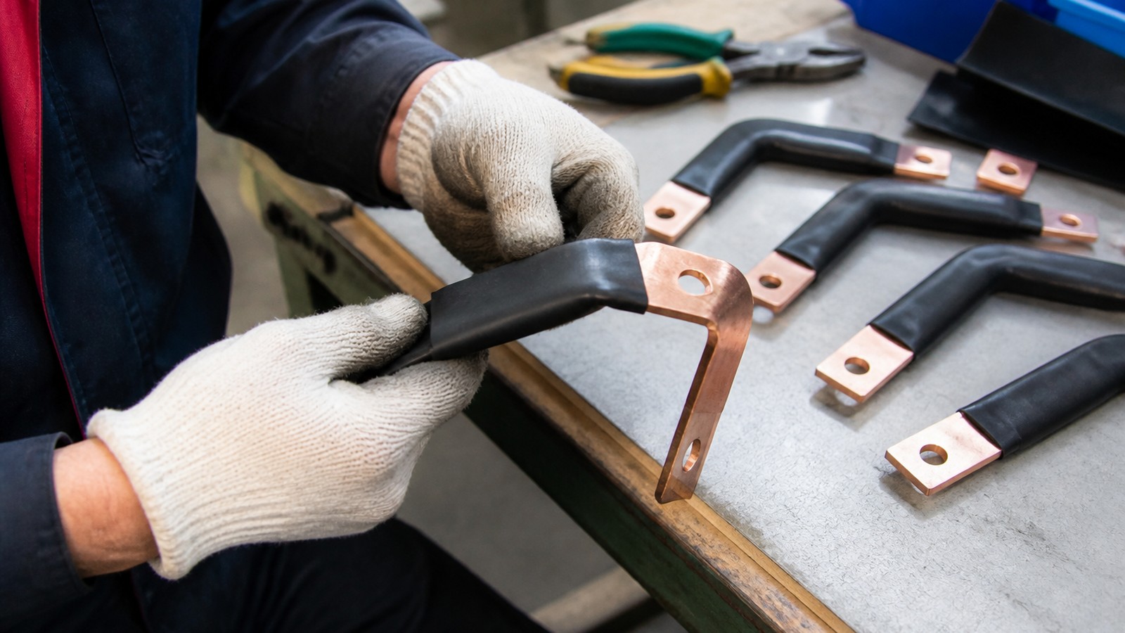
Custom busbar manufacturing
Engineering details are organized around material, tolerance, surface finish, inspection, and production readiness.
Use the inquiry module to send drawings, quantities, standards, and delivery targets for a practical manufacturing review.
Service Details
Engineering-first guidance for specifying insulated copper and aluminum busbars used in EV battery systems, energy storage, power electronics, charging equipment, switchgear, and industrial power distribution.
BusbarMFG manufactures drawing-based insulated busbars and related high-current interconnect components. This guide consolidates practical insulation selection, design, and specification tips to help engineering-led OEM teams progress from drawing to production-ready parts.
Note: Project feasibility and specific process capability (e.g., coating types, special sleeves, overmolded elements) are confirmed during technical review based on your drawings and requirements.
Why Insulate a Busbar?
Insulation on a busbar provides electrical protection and packaging efficiency while maintaining repeatable assembly. Compared to bare busbars and cable harnesses, insulated busbars can:
- Improve creepage/clearance in tight envelopes
- Reduce assembly variation and error risk
- Enable lower-inductance power distribution vs. cable
- Support functional, basic, double, or reinforced insulation strategies
- Provide color coding for high-voltage and phase identification
- Enhance safety and serviceability
Common applications include EV battery interconnects, inverter DC links, ESS modules, DC bus assemblies, and compact switchgear power distribution.
Common Insulation Options
BusbarMFG supports insulated configurations such as heat-shrink, coated, sleeved, or otherwise insulated busbars. Selection depends on voltage class, environment, thermal limits, assembly needs, and cost.
- Heat-shrink sleeving
- Widely used; good coverage around flat or formed busbars with controlled wall thickness
- Available in standard and high-shrink ratios, various dielectric strengths, and HV orange
- Typical features: cutouts for terminals, strip-back for bolted joints, adhesive-lined variants for moisture resistance
- Dip coating / liquid coating
- Conformal coating around complex shaped parts; consistent surface coverage
- Suitable for compact packaging and smooth edges
- Material options include PVC, polyamide, epoxy-based systems, etc., subject to project review
- Powder coating (electrically insulating grades)
- Durable film, suitable for mechanical robustness and abrasion resistance
- Requires controlled surface preparation and bake cycles; thickness uniformity is key
- Sleeves and wraps
- PET, PTFE, polyolefin, or woven glass-based sleeves for abrasion and dielectric performance
- Often combined with adhesive tapes or spot bonds to stabilize during assembly
- Laminated/insulated stack-ups
- When used as laminated busbars or layered constructions, dielectric films (e.g., polyimide, polyester, PPS) are integrated between conductors for low-inductance power distribution
- Requires careful thermal and mechanical design; confirm during technical review
Note: Final process choice and material grade are confirmed per project requirements. If your design needs specialized insulation (e.g., UL94 V-0 classes, HV orange compliance, specific chemistry resistance), include it in your RFQ.
Key Design Considerations
- Voltage and insulation class
- Define basic, supplementary, double, or reinforced insulation needs
- For >600 V systems, evaluate partial discharge (PD) risk and corona onset, especially at edges and sharp transitions
- Creepage and clearance
- Align with your applicable standards (e.g., IEC/UL frameworks used in your product domain)
- Increase creepage over contaminated or humid environments; derate for pollution degree and altitude as needed
- Dielectric strength and IR
- Specify required dielectric withstand (hipot) and insulation resistance values
- Include test voltages, dwell times, and pass/fail criteria
- Thermal requirements
- Define continuous and peak temperature limits; consider temperature rise of the conductor at rated current
- Choose insulation with suitable thermal class and aging performance
- Evaluate thermal softening or embrittlement versus service environment
- Chemical and environmental exposure
- EV/ESS: coolants, oils, and potential electrolyte exposure
- Industrial: dust, moisture, cleaning solvents
- Choose materials with proven compatibility and moisture resistance
- Mechanical robustness
- Abrasion resistance, vibration tolerance, and flex during assembly
- Edge radiusing and burr control to avoid insulation damage
- Flammability and compliance
- If required, specify flammability ratings (e.g., UL94 V-0) or other market-specific compliance criteria
- Reference only the standards actually applicable to your product; test plans to be defined during technical review
- Color coding and marking
- HV orange for automotive/EV conventions
- Phase color, polarity marking, or barcodes/labels as required
Geometry and DFM Tips for Insulated Busbars
- Edge and surface preparation
- Specify minimum edge radius or break sharp edges to prevent pinholes and PD-prone edges
- Control burr height and surface finish before insulation
- Strip-back areas
- Clearly define exposed conductor zones for bolted joints, welds, or crimped interfaces
- Include dimensions, tolerances, and positional callouts for strip-back lengths and offsets
- Hole and interface detailing
- Allow for washers, sleeves, or bushings where dielectric separation is critical
- Consider grommets or insulating bushings through panels/enclosures
- Bend and form sequencing
- Confirm if insulation is applied before or after forming; most coatings/sleeves are applied after forming
- For heat-shrink, maintain bend radii that avoid post-shrink cracking or thinning
- Thickness and coverage
- Specify nominal insulation thickness and allowable variation
- Define coverage areas, do-not-coat surfaces, and target fillet radii at corners for consistent film build
- Plating and insulation interaction
- Many programs plate (tin, nickel, silver) before insulation for joint quality
- Verify adhesion and process compatibility; some coatings require specific surface prep over plated copper
- Note potential outgassing during bake processes and its effect on adhesion and PD
- Flexible and laminated structures
- For copper foil laminations or flexible links, define bend ranges, fatigue expectations, and insulative film properties
- Confirm clamping interfaces and stress relief to avoid insulation damage
Application-Specific Notes
- EV battery interconnects
- HV orange insulation; double/reinforced insulation may be required depending on architecture
- Minimize PD via smooth edges and appropriate creepage/clearance
- Validate compatibility with coolants and cell vent byproducts; consider adhesive-lined heat-shrink at terminations
- Energy storage systems (ESS)
- Emphasize creepage/clearance for higher system voltages and outdoor humidity
- Consider coating thickness targets and spark testing for pinhole detection
- Power electronics (inverters, UPS, PCS)
- Focus on low-inductance routing; insulation must not compromise compact layering
- Validate thermal performance around heat sources and heatsinks
- Charging equipment and switchgear
- Mechanical robustness and abrasion resistance are critical
- Consider sleeves/coatings that withstand installation handling and maintenance cycles
Verification and Test Practices
Specify the tests needed for your program. Typical checks include:
- Dielectric withstand (hipot) at defined test voltage and dwell
- Insulation resistance (IR) at specified voltage and environment
- Pinhole/spark testing for coated or dipped insulation
- Thickness measurement and coverage verification
- Adhesion/peel tests where applicable
- Visual inspection for voids, runs, blisters, or edge exposures
- Environmental conditioning (humidity, temperature cycles) as required by your qualification plan
Note: Test plans and acceptance criteria are confirmed for each project during engineering review.
How to Specify Insulated Busbars on Drawings
Include the following information for a faster and more accurate technical review:
- Base conductor
- Copper or aluminum grade, thickness, and width
- Plating (tin, nickel, silver) and plating thickness if required
- Insulation
- Type: heat-shrink, coating, sleeve, laminated stack, or other
- Material and rating requirements (e.g., dielectric strength, UL94 class, temperature class)
- Color (e.g., HV orange) and surface finish expectations
- Nominal thickness and allowable variation
- Coverage map with strip-back areas; callouts for do-not-coat surfaces
- Crease/edge radii, chamfers, and protected edges
- Any specific standards or test requirements (hipot, IR, spark test)
- Geometry and interfaces
- Final formed geometry with tolerances
- Hole sizes, slot features, and interface hardware assumptions
- Minimum bend radii and assembly constraints
- Performance requirements
- Continuous/peak current and acceptable temperature rise
- Environmental conditions (humidity, chemicals, altitude)
- Packaging constraints and assembly sequencing notes
- Quantity and timeline
- Prototype/validation/production phases
- Target dates for samples and production ramp
RFQ Workflow with BusbarMFG
Our engineering-led RFQ process starts from your drawing or model and application requirements. We review material selection, thickness, insulation, plating, bends, holes, interfaces, and connection methods. Programs often begin with prototypes or validation batches and progress to repeat production as requirements are confirmed.
To enable an efficient review, please provide:
- Drawings/models with all busbar features and insulation coverage marked
- Base material and plating requirements
- Insulation type, color, thickness, dielectric/test requirements
- Quantities for prototype and production
- Application description and target date
BusbarMFG does not publish unverified certifications, equipment lists, tolerances, lead times, production capacity, or customer claims. Project-specific requirements are confirmed during technical review.
Request Pricing for Busbar Insulation Guide
Share drawings, material grade, tolerance, surface finish, quantity, and delivery schedule. BusbarMFG will review the requirement and respond with the next step.
Engineering RFQ
Upload Your Drawing
Share drawings or models, material, plating or insulation requirements, quantity, application, and target date. We will review the technical requirements before confirming manufacturing options.
Email: info@busbarmfg.com
Address: Huali Industrial Park, Xianghe Road, Dalang Town, Dongguan City, Guangdong Province, China